KAYA MKI
2017 - 2021Completed.
KAYA is a passion project aimed at solving the annoying problem of getting around Auckland City efficiently while studying at university. As many students and people living in Auckland know all too well, the public transportation network is appalling and expensive. Combined with variable hilly terrain means that it is tough to get from place to place efficiently. After having missed too many buses because they ran early or were full and being late to class too many times, project KAYA was born.
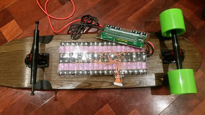
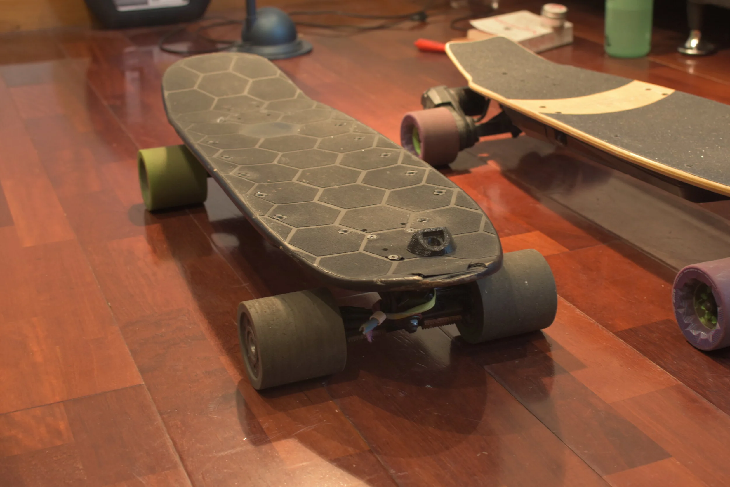
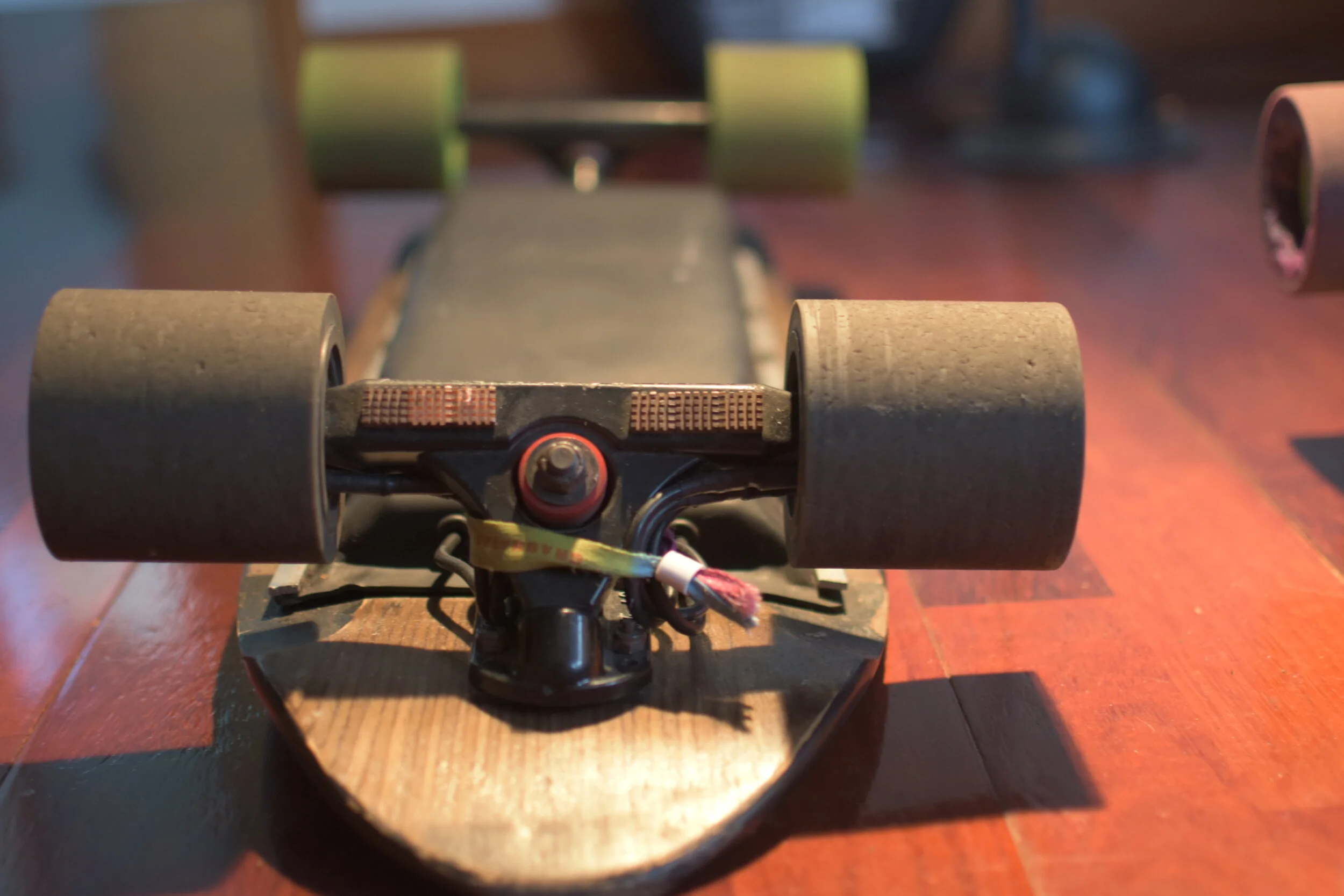
KAYA MKI is a custom dual hub electric motor running two FOCBOXes based on the open-source VESC project by Benjamin Vedder. This set-up is powered by a custom 12s3p Samsung 30Q battery pack with cell level fusing and a built-in battery management system (BMS) and controlled by a pulse-position modulation (PPM) signal through an off the shelf 2.4 GHz wireless remote.
Unfortunately, KAYA did not fully solve the ‘late to the class problem’ as it allows users to blast through traffic at a recorded top speed of 56km/h and wake up 20 mins before lectures start. However, KAYA has reduced commute times from 30+ mins down to 15 mins and makes commuting fun by allowing the user to ‘surf through and around cars. The future of mass transport should enable users to get where they want to go when they want to go, and users should not have to adhere to a fixed schedule; fun commutes should be the norm.
Build.
RIDE.
Parts list (shortened)
SkateShred 35" Dark wood Base
Dual Hummie Hubs
Dual Enertion FOCBOXs
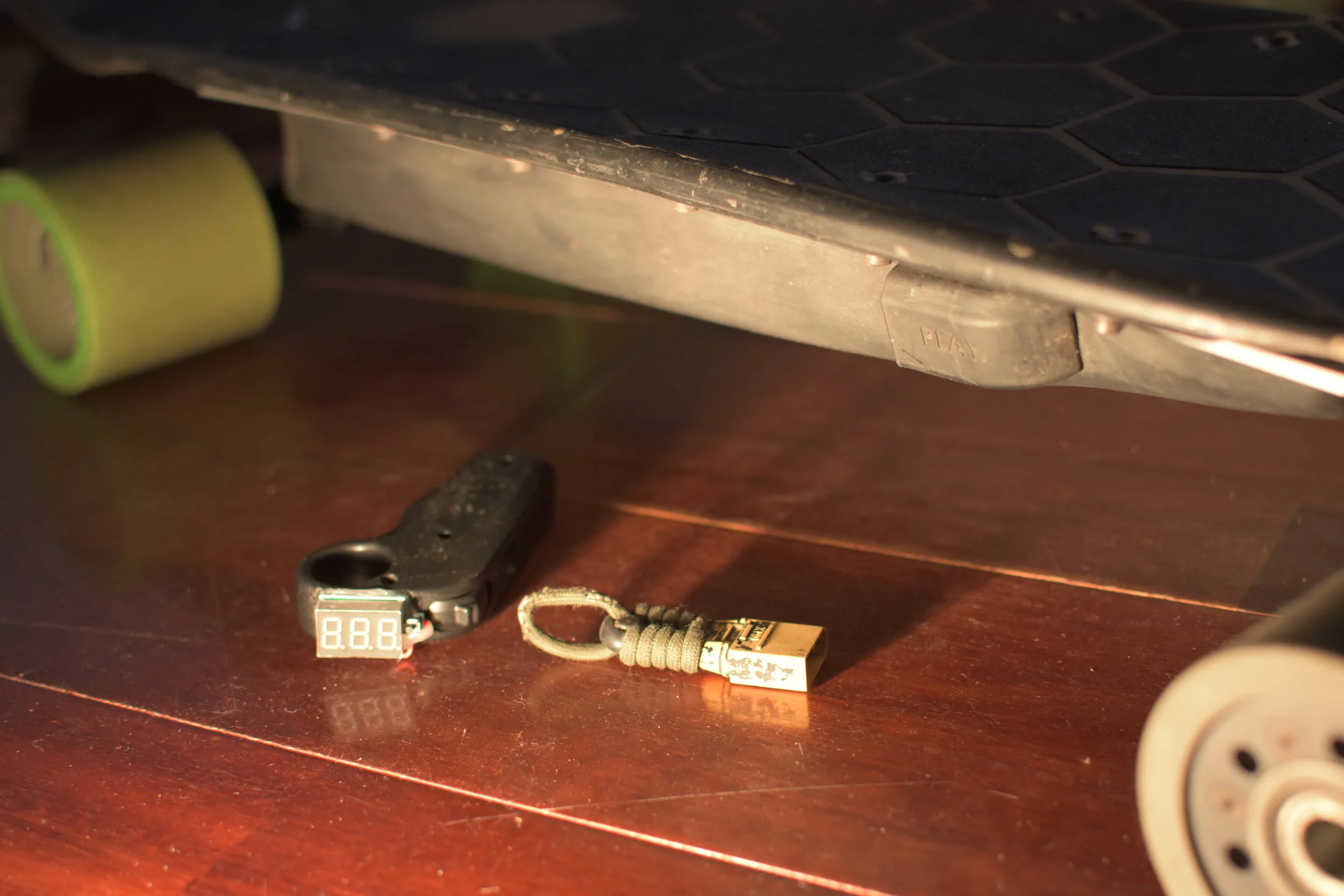
Winning Mini Remote x Enertion Remote x Custom battery readout
Black Paris trucks with stock bushings
83mm Abec front wheels
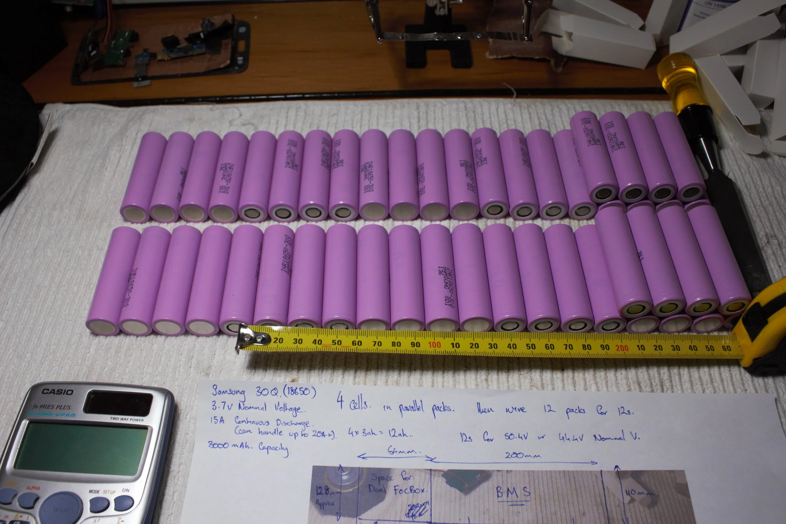
Homemade 12s3p Samsung 30Q Pack with cell level fuses
12s 80A Supower BMS For charging and discharge
Homemade Kydex enclosure
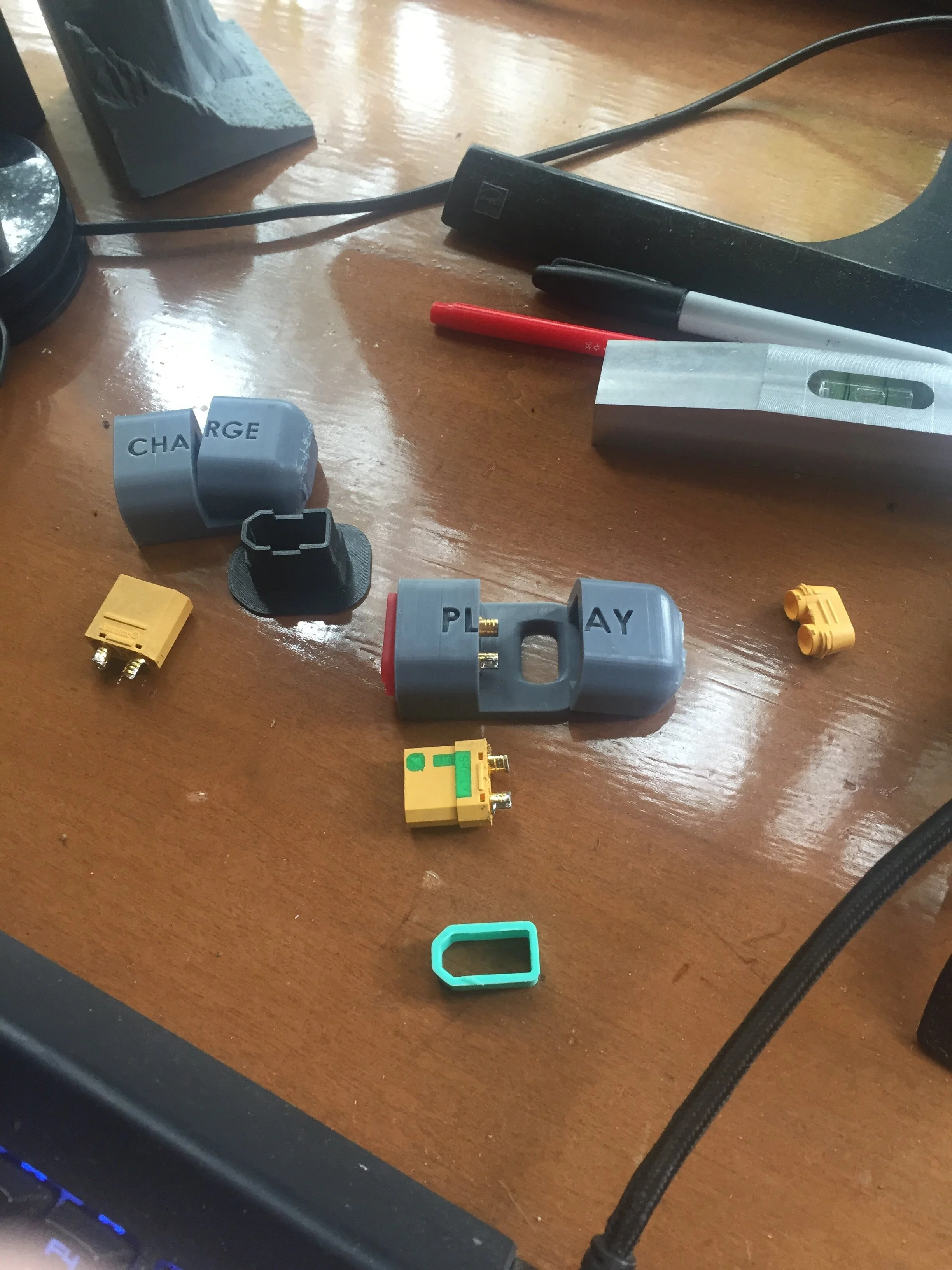
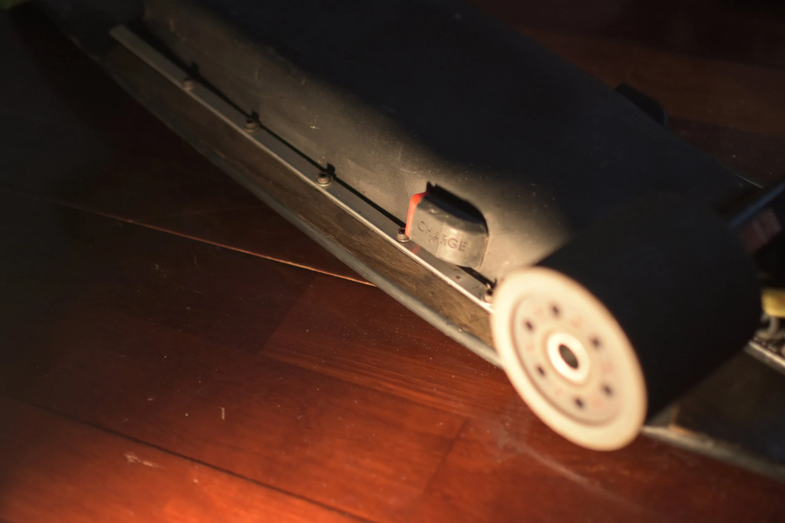
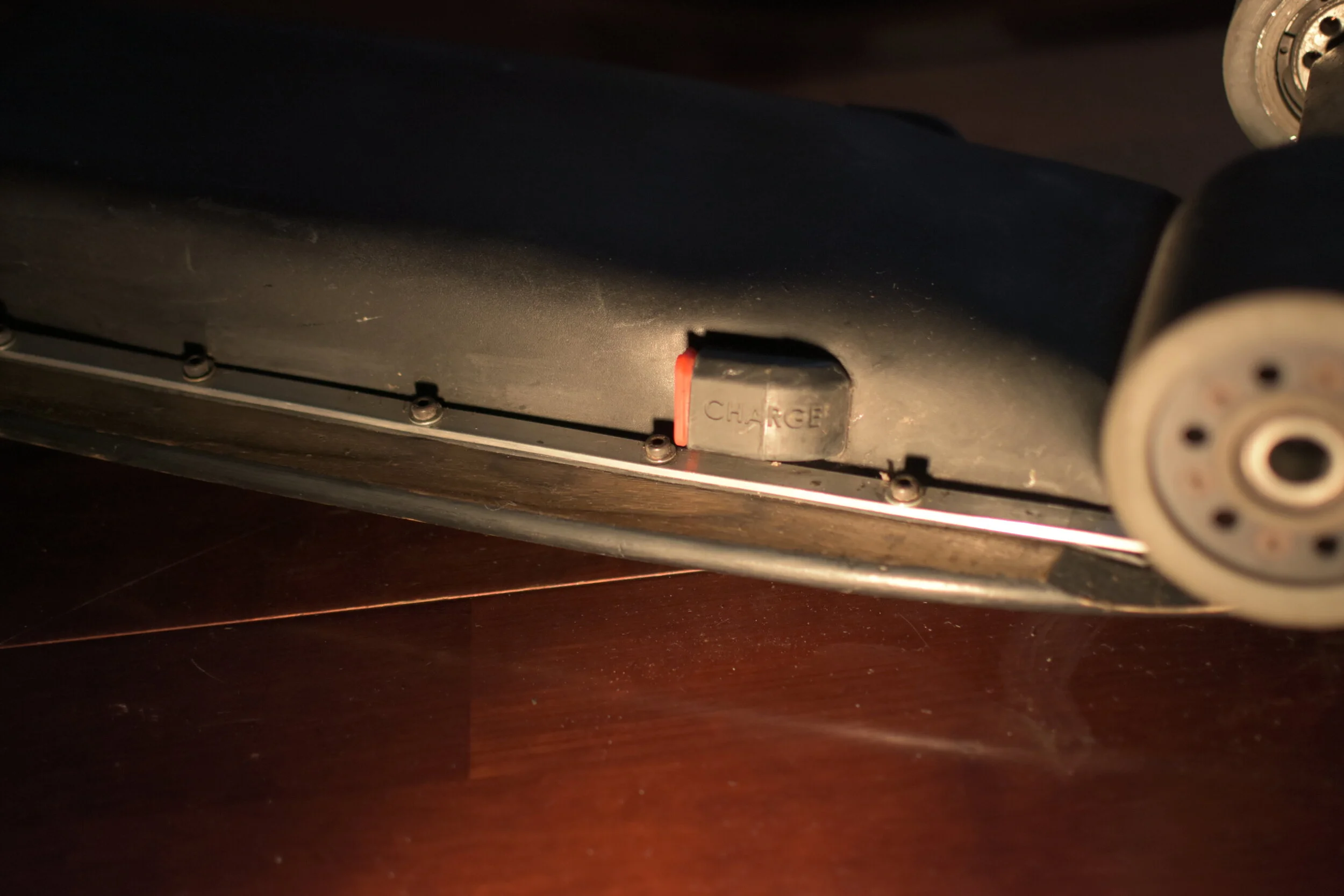
Custom Charge and Play Ports
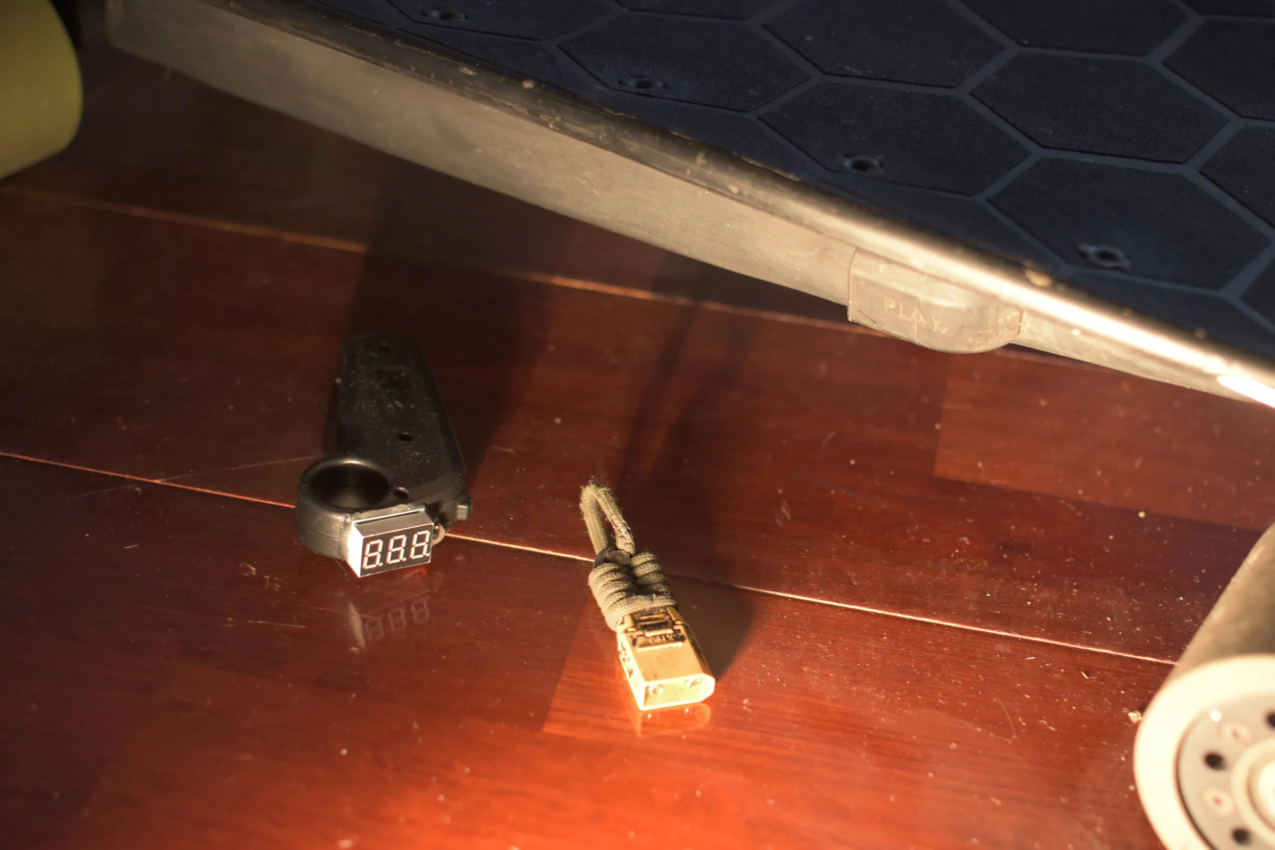
Custom AntiSpark Loop Harness with Key
3D printed PLA footstop
BUild Information
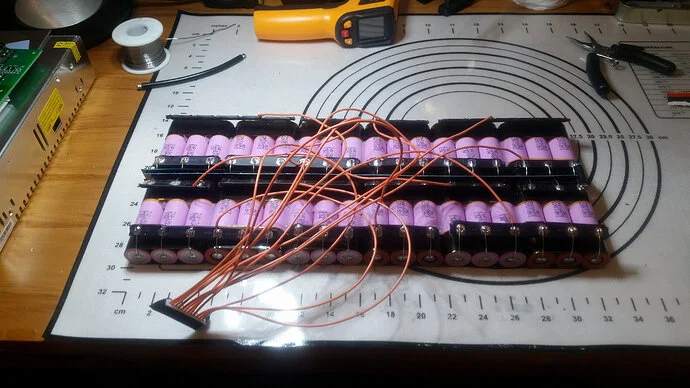
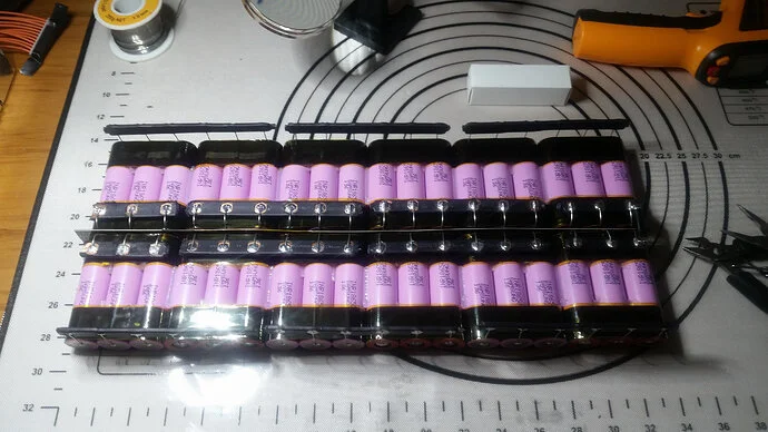
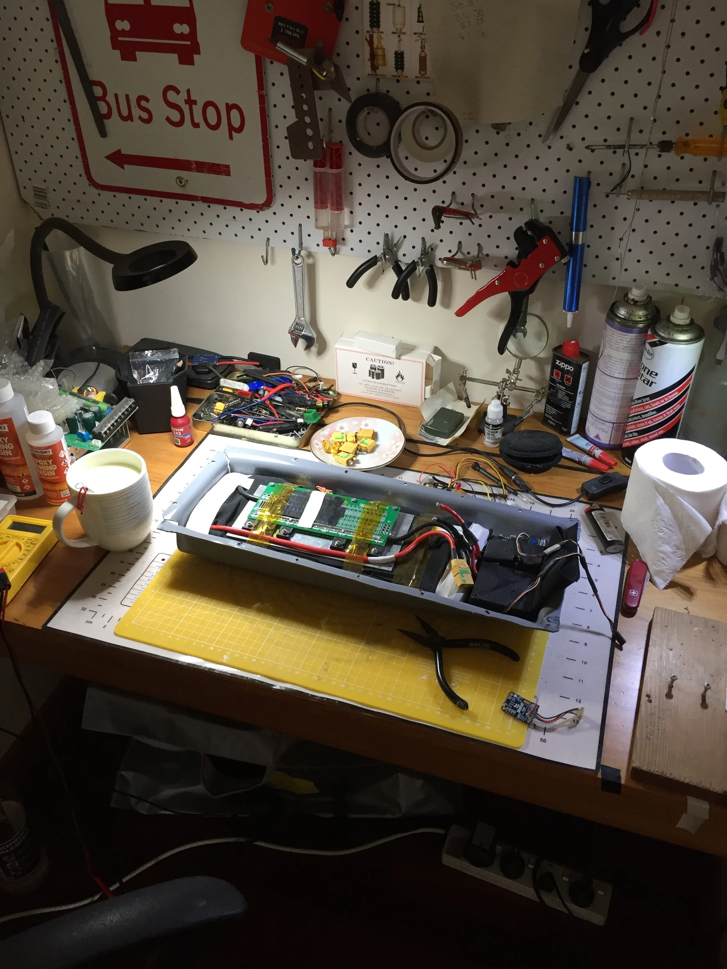
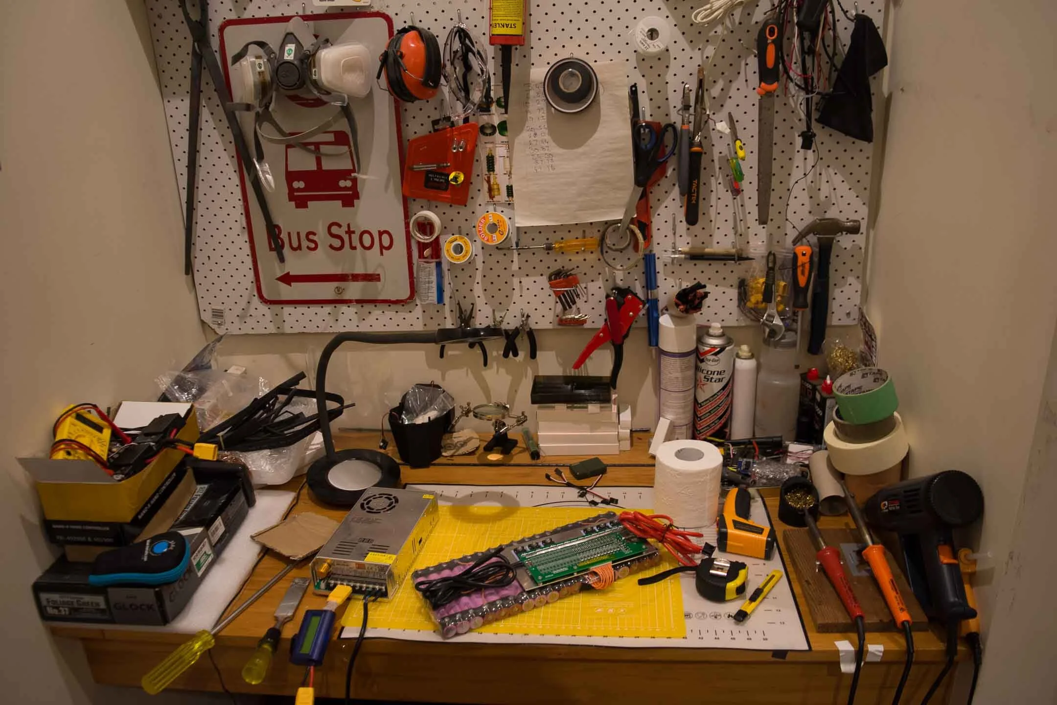
The individual cells were siliconed together in groups of three for vibration resistance (after checking individual cell voltage) and then wrapped in a layer of electrical tape followed by a layer of Kapton tape. Each cell has fish paper over the positive terminal to prevent abrasion, creating shorts. The cells were directly soldered with a fat tipped 80w soldering iron, which created a perfect joint. There is a lot of debate over soldering vs welding for cell health; however, you can not beat a solid joint that is both strong (resistant to vibration) and highly conductive from the first-principles point of view. The busbars are made from a 2mm pure copper sheet cut into 8mm wide bars; the fuse wire is 22AWG tinned copper wire from Remmington Industries. Then the balance wires were attached while checking that the voltages matched the calculations. The pack was then heat shrank in clear heat shrink to allow for visual inspection of the cells, fuse wires, and busbars. The exposed copper received some neutral cure silicone to slow down corrosion.
The charger is just a Meanwell variable power supply meant to power a CNC/3D printer etc. It was chosen because it has perfect safety features (reverse voltage protection, high-temperature cutoff, high voltage cutoff etc.), the variable voltage, which allows the user to set the charge to ~90% to prolong battery life, and a constant current/constant voltage (CC/CV) curve which matches how Lithium-Ion batteries should be charged. This power supply unit (PSU) is paired with a simple WattsUp power monitor that shows the power passing through and the number of watt-hours charged. This is actually the second power supply charger on this project as the first one blew up when first charging the battery; that was scary and was later ruled to be due to poor manufacturing of the PSU (don't buy this).
The grip tape is custom cut through using a trotec speedy 300 and is hex patterned because that was cool, and no one was doing it in 2018. The enclosure has had two revisions, both being made out of Kydex, commonly used for gun holsters. Kydex is great due to its ease to work with, malleability when heated, and strength/impact resistance when hardened. The first Kydex enclosure was made by heating the sheet of Kydex and pressing it over the battery and control units leading to a tight and accurate fit. This, however, was a rush job. Although it lasted around 500 km, it eventually broke after a driver pulled in front of Kuan when he was riding to work, causing him to rear-end the car with KAYA ending up under the car, suffering some damage. This led to the second revision, more time was taken with this enclosure, and it has ended up being exactly what was envisioned all the way back in 2017 (the last 6 photos are the finished project).
The remote has also had a couple of revisions, with the first version being an off the shelf 2.4 GHz remote from aliexpress. This remote worked well until it started cutting off whilst the user went downhill, leading to many bails. After some analysis, it was discovered that the remote would malfunction around residential power transformers; this is because they emit electromagnetic fields which induced currents within the remote and because the remote was not designed with EMI in mind, caused it to lose power/reset temporarily This led to the purchase of a newer remote which still worked off of the 2.4GHz band but was designed to avoid EMI. However, the ergonomics of the new remote were horrible, so the new electronics were transplanted into the casing on the old remote. Finally, a digital voltage readout was wired with a simple push-button switch straight to the battery terminals of the new remote to inform the user on how much charge the remote has left. It purposefully only displays the battery's voltage, meaning that only those who know that the numbers mean know how much charge the remote has left.
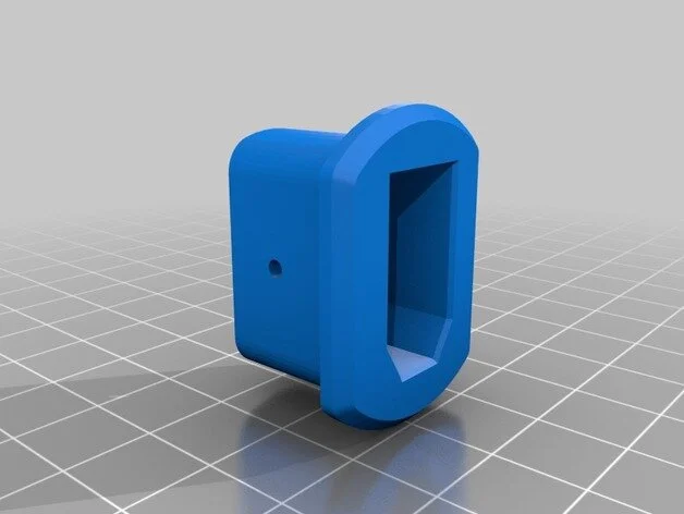
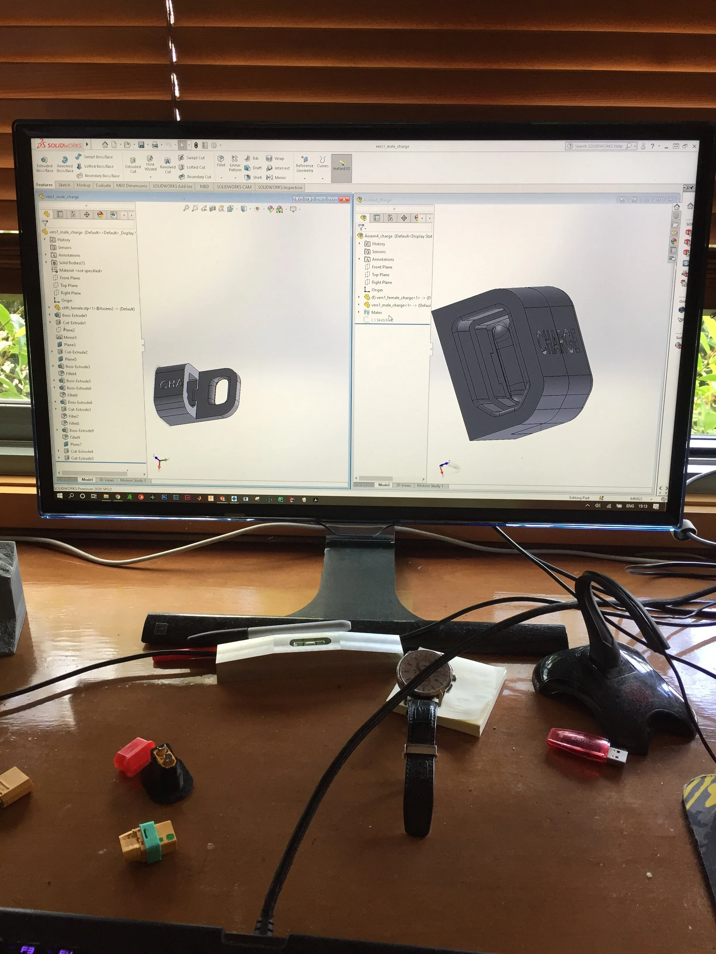
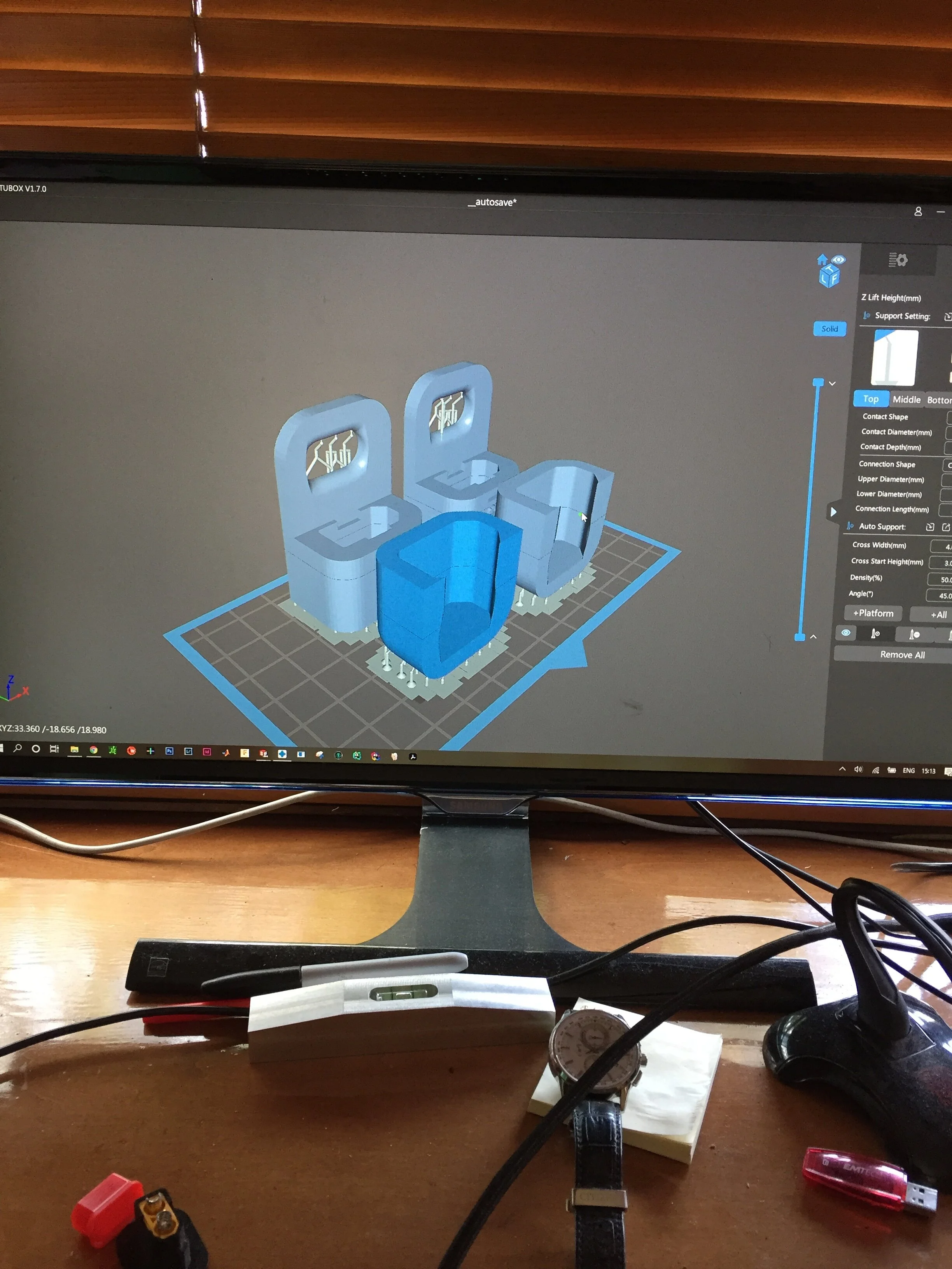
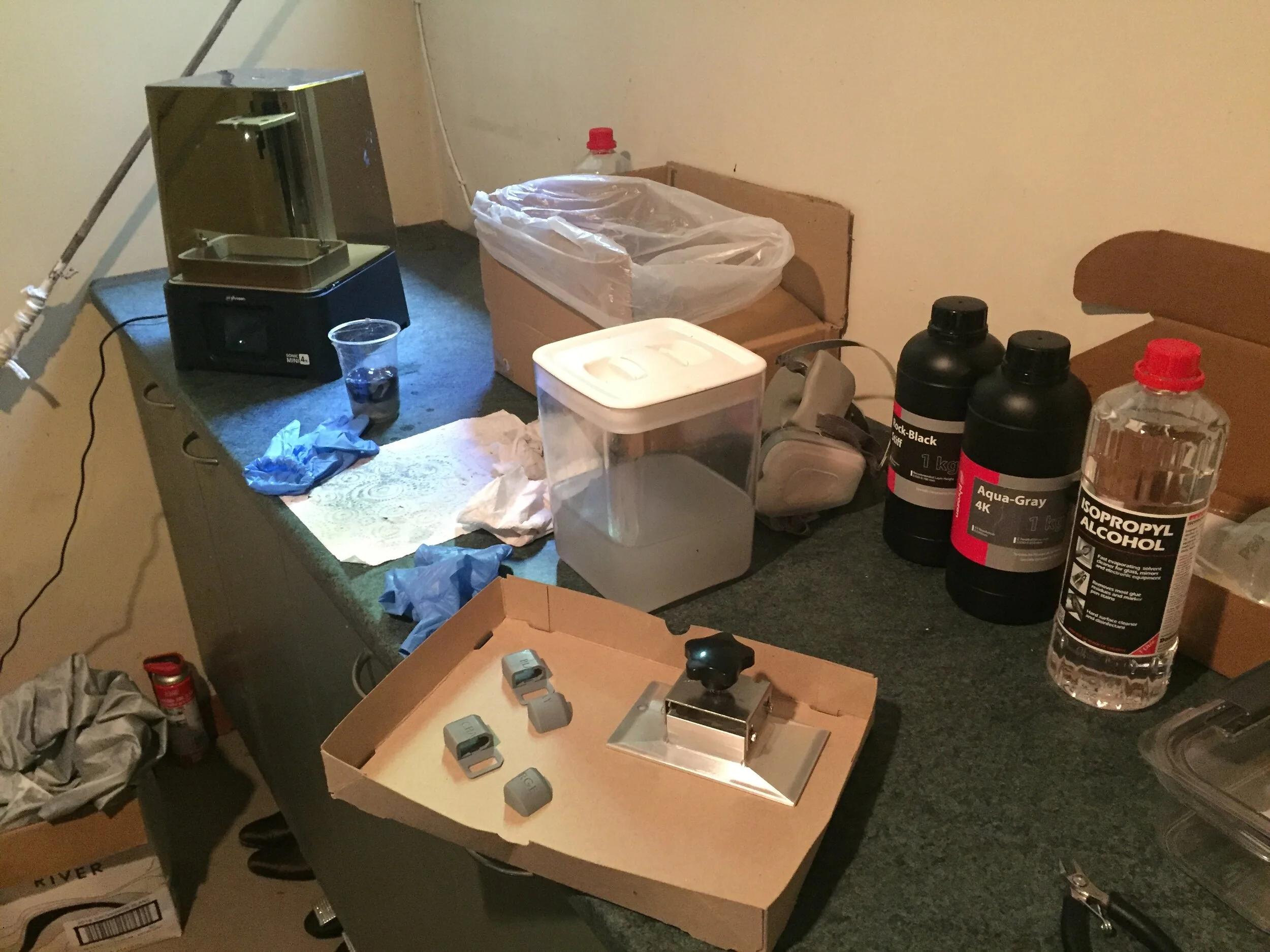
The charge/play ports have had many different revisions, with the first ones consisting of the respective wires being hot glued to the side of the enclosure. The latest version looks very clean. It consists of two streamline covers which house the charge port wires, and the ‘play’ port wires which are basically the switch. Because both charge wires and play/switch wires use XT90s connectors for their current carrying capabilities and their antispark resistor, a red silicone cover is affixed to the charge port at all times unless the board is being charged. This is because the wiring harness is wired such that if the play/switch port completes the circuit whereas the charge port is connected in parallel with the battery. If the user puts the key into the charge port, this will short the battery, and although the BMS has short circuit detection, it should not be tested. The ports are printed on a Phrozen Sonic Mini 4K with Aqua-Gray 4K resin.
Finally, a wireless Bluetooth module based on the nrf51_vesc project was added to the board to provide remote telemetry, allowing the user to monitor the board’s vitals such as speed, board battery levels, erpm, current draw, current regen etc. through a mobile phone. The board has also been recently rewired to be front-wheel drive as it provides greater braking power as it is primarily a commuting vehicle.
Photos taken by a Nikon D7200.


